Generally, the majority of electrical devices are made up by a mechanical part and an electronic part. This electrical part consists in printedcircuit boards, where the different components are connected by means of copper pathways on a board made of insulating material.
The first step to obtain one of theseprinted circuit boards(PCBs) is to design it using one of the specific tools on the market. One of the most popular ones is OrCAD.
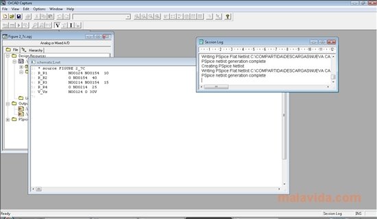
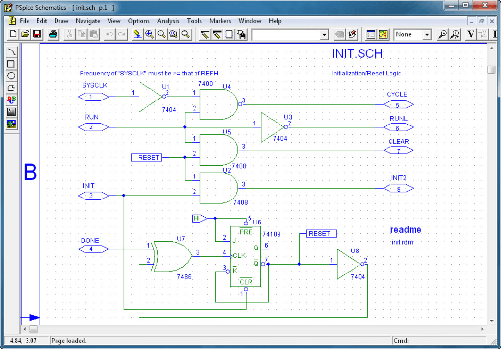
OrCAD is the most powerful and intuitive tool to design printed circuit boards. The demo version offers you the possibility to evaluate the following functions: OrCADCapture, OrCADCapture CIS Option, PSpice A/D, PSpice A/A, OrCADPCB Editor and SPECCTRA.
The basic steps that have to be taken to designa printed circuit board with OrCAD are:
1. Design the circuit by creating the schematic in the 'Capture' module.
2. Generate the circuit's netlist.
3. Import the netlist to 'LayoutPlus'.
4. Place the components and trace the pathways.
5. Generate the files of its design.
Once the design of the copper pathways on the board has been finished, and we have simulated the behavior of the design, the next step will be to design the PCB from an insulating material, like for example a photosensitive fiberglass board.
- Oct 12, 2018 orcad with crack orcad with crack free download orcad with pspice orcad with matlab orcad 9.2 free download with crack orcad 10.5 installation with crack orcad 17.2 download with crack pcb design.
- OrCAD (All Products) is not available for Mac but there are some alternatives that runs on macOS with similar functionality. The most popular Mac alternative is KiCad, which is both free and Open Source. If that doesn't suit you, our users have ranked 40 alternatives to OrCAD (All Products) and ten of them are available for Mac so hopefully you.
Iso mac os for pc. ♦ Click on “PSPICE model and symbol ” for OrCAD PSpice platform. ♦ Click on “LTspice model and symbol ” for LTSpice simulator. A practical introduction to electronic. 1994 nitro owners manual. It will start downloading the zip file containing all models available for the complete SuperFet 3 family.


Orcad Pspice For Mac Os

Orcad Pspice For Mac Download

Orcad Pspice For Mac
This download requires a ZIP compatible compressor. This program also requires that you have .NET Framework 2.0 or above installed. It's necessary to register to download this application. Since it's a trial version, the size and the complexity of the designs are limited.


Comments are closed.